Measuring resistance using a potentiometer
The first assignment this week was to make a capacitive sensor to measure a physical quantity with a microcontroller. I decided to use a potentiometer to measure the amount of resistance produced. A potentiometer is a voltage divider with a movable contact. By passing voltage through a potentiometer and into an analog input on my board, I measured the amount of resistance produced by the potentiometer as an analog value. I Below is an outline of my process:
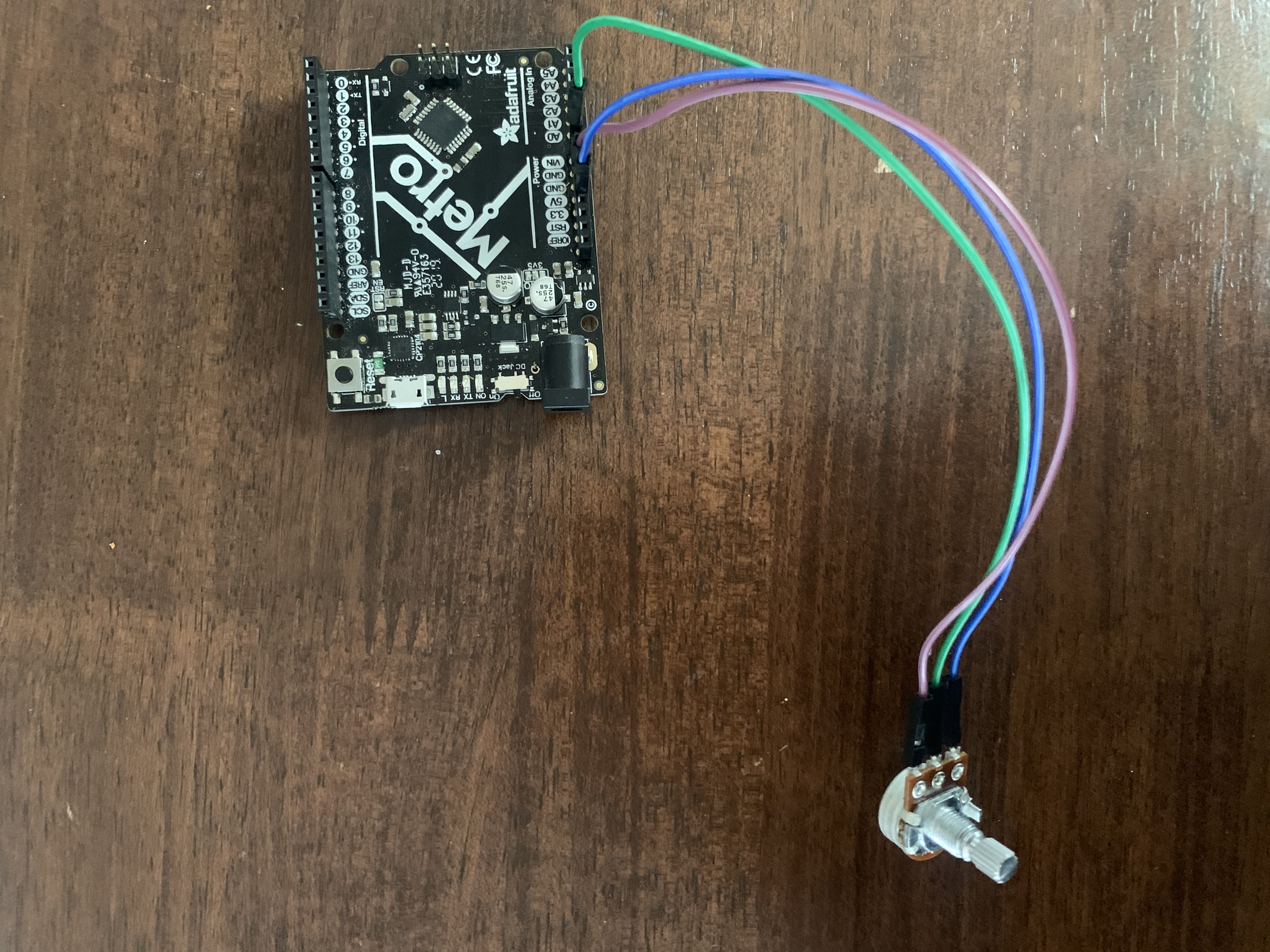
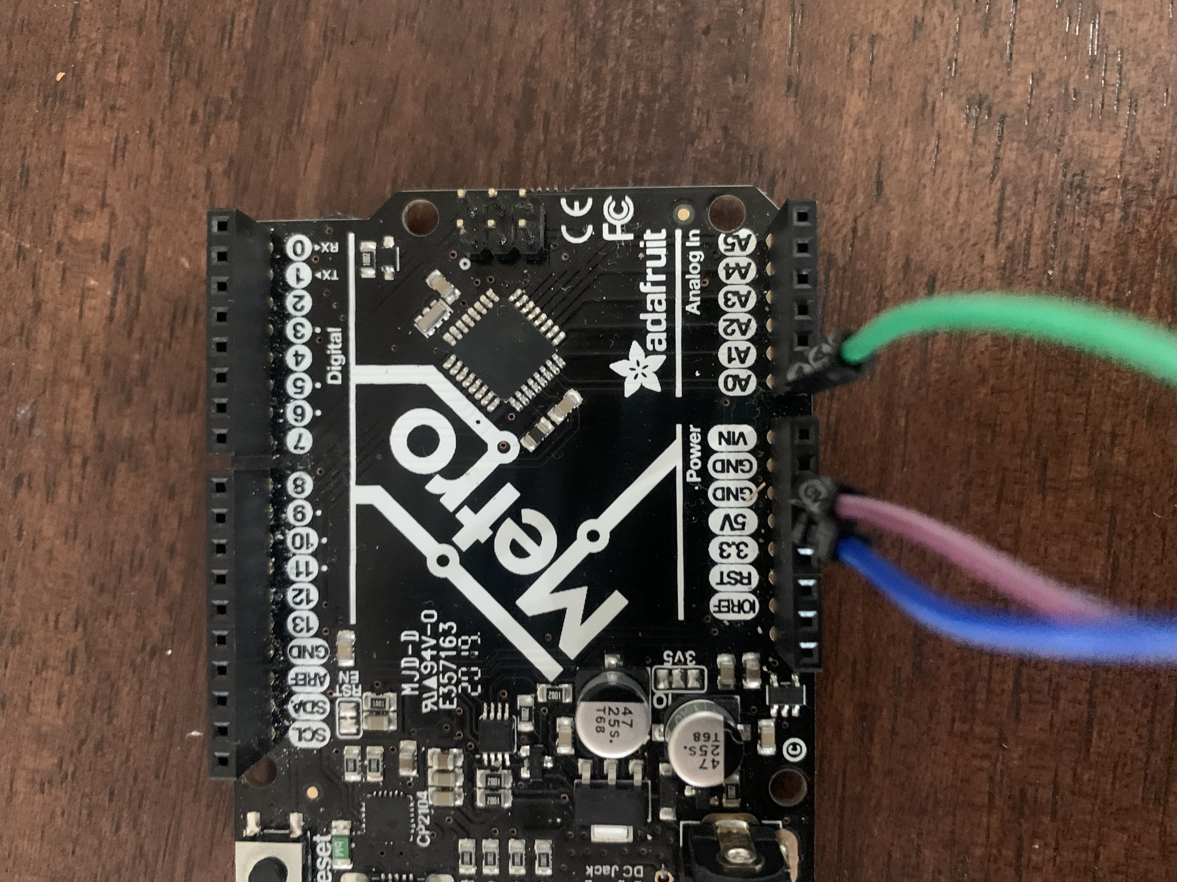
- First, I built a simple circuit by connecting three wires from the potentiometer to my Arduino Uno: first from left outer pin to ground, second from right outer pin to 5V, and third from middle pin to analog pin A0.
- Next, I connected the circuit to my computer. I created a new Arduino sketch using the analogRead() function that would take the input voltage and converts it to to a value between 0 and 1023 that is proportional to the amount of voltage being applied to the pin.
- After uploading the code above to the board, I opened the Serial Monitor in the Arduino Software and changed the drop-down to 9600 bits of data. As I turned the shaft of the potentiometer, the values on the monitor responded. I saw a steady stream of values ranging from 0-1023. When I turn the shaft all the way in one direction, the input value is 0 meaning 0 volts are going to the pint. In the other opposite direction, there are 5 volts going to the pin and input value is 1023.
- Next, I opened a new Serial Plotter window to visualize the measurements in a graph. As I turned the potentiometer, I could graphically see changes in the Arduino-sensed reistance data (as shown below).
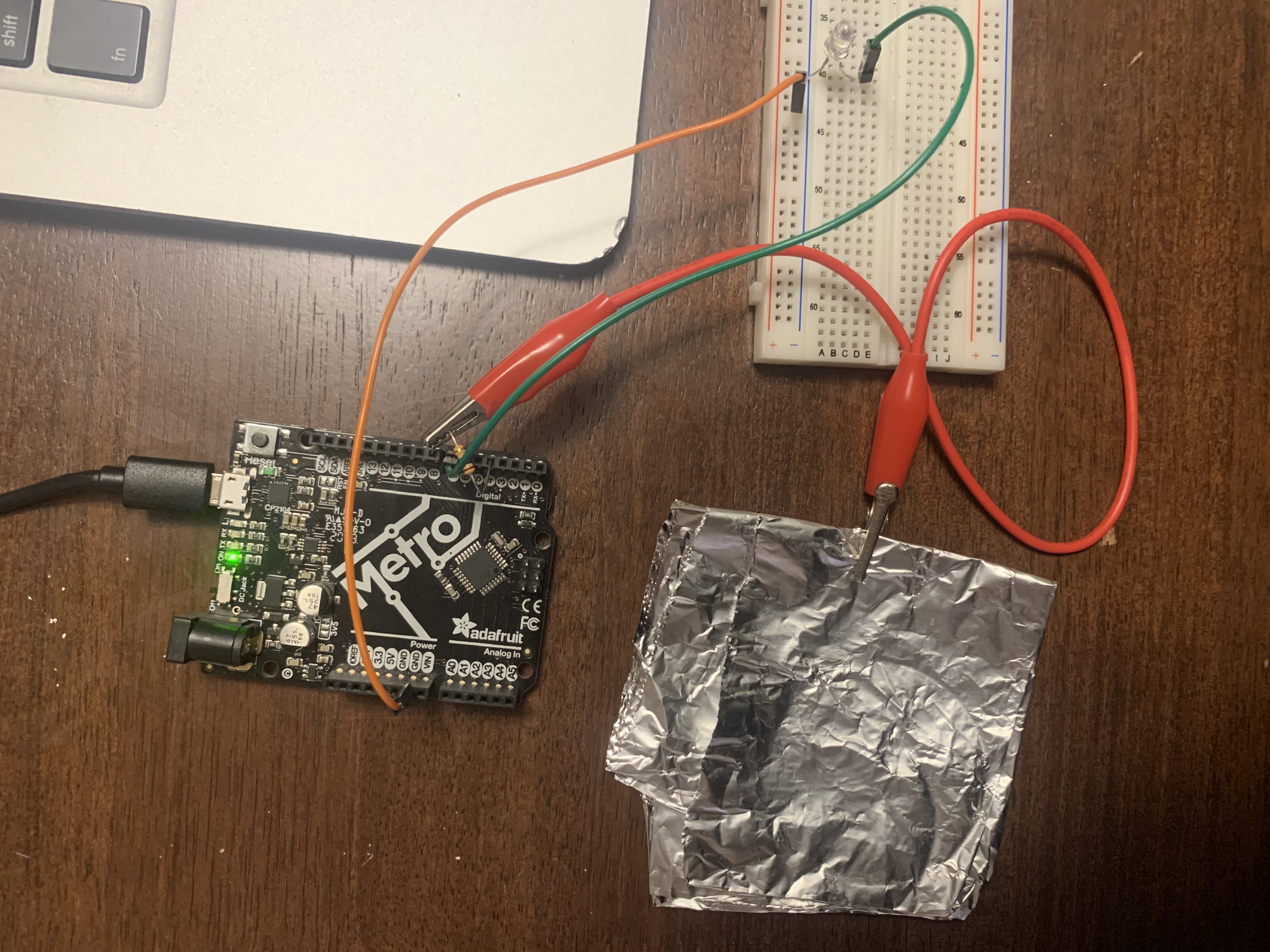
- First, I built a simple circuit consisting of the following hardware: an Arduino Uno, 1 M ohm resistor, a breadboard, white LED, a square of aluminium foil, and some jumper wires. I plugged in the resistor directly on the Arduino digital pins 4 and 8. To create a touch plate, I folded up a piece of aluminium foil. I used a jumper wire to connect the resistor on pin 8 to the touch plate. On the breadboard, I plugged in the LED by connecting the -ve side to GND and +ve side to digital pin 7.
- Next, I connected the circuit to my computer. I created a new sketch that would turn an LED on to signal contact on the touch plate. To run this code, the open-source CapacitiveSensor Library should be first downloaded and installed.
- After uploading the code above to the board, I opened the Serial Monitor in the Arduino Software. As I touch the conductive surface, the sensor reads the pulse that changes with the proximity of contact (see video). Both the serial plotter and serial monitor show spikes in values when my hand touches the plate. These signal strength values decrease as proximity decreases.
Images of simple circuit
Copy of analogRead() code to measure resistance produced by potentiometer
        // the setup routine runs once when you press reset:
void setup() {
  // initialize serial communication at 9600 bits per second:
  Serial.begin(9600);
}

// the loop routine runs over and over again forever:
void loop() {
  // read the input on analog pin 0:
  int sensorValue = analogRead(A0);
  // print out the value you read:
  Serial.println(sensorValue);
  delay(1);        // delay in between reads for stability
}
Screen recording of serial monitor values as I turn potentiometer shaft
Screen recording of serial plotter graph as I turn potentiometer shaft
Making a capacitive sensor
For the second part of the assignment, I decided to make a capacitive touch sensor which would measure and sense the electrical capacitance of the human body. This sensor would detect changes in electromagnetic field based on changes in human contact to a metal plate. To create this sensor, I completed the following steps:
Image of simple circuit for capacitive sensor
Copy of capacitive sensing code:
        // #include

#include


CapacitiveSensor   cs_4_8 = CapacitiveSensor(4,8); // 1M resistor between pins 4 & 8, pin 8 is sensor pin, add a wire and or foil

void setup()
{
   cs_4_8.set_CS_AutocaL_Millis(0xFFFFFFFF);// turn off autocalibrate on channel 1 - just as an example
   Serial.begin(9600);
   pinMode(7,OUTPUT);
}

void loop()
{
 long sensor1 =  cs_4_8.capacitiveSensor(50);

    Serial.println(sensor1);  // print sensor output
   if(sensor1 >= 1000)
   {
    digitalWrite(7,HIGH);
   }
   else{
    digitalWrite(7,LOW);
   }
}
}
Demonstration of capacitive sensing with LED turning on
Screen recordings of serial monitor and plotter capturing changes in sensor signal strength: