The Assignment
This week's assignment was to create a kinetic sculpture composed of pieces cut from at least two different materials. Other requirements include: at least one static joint, at least one prismatic or revolute joint, and (optional) circuitry to move the sculpture. I decided to take on this assignment as a way to showcase what I learned about using different hand tools and mechanics this week. Given that I am coming into this class with very litle background knowledge on digital and physical fabrication, this week was exciting as it gave me a chance to learn a wide range of techniques.
The Initial Design
I began by researching examples of kinetic scultpures and the processes used to make them move. I then began brainstorming ideas of sculptures that would have some practical purpose in my life. I settled on designing a sculpture I could give to our neighbor who has young children my roommates and I often babysit for. We used to make sock puppets with them and they were always very excited to make them. I decided to take this one step further and make a mechanical puppet I could gift them. Because I was designing this with children in mind, I wanted to include simple mechanics. Thus, as included below, I designed a basic mechanical puppet with a DC motor attached.
Initial Sketch
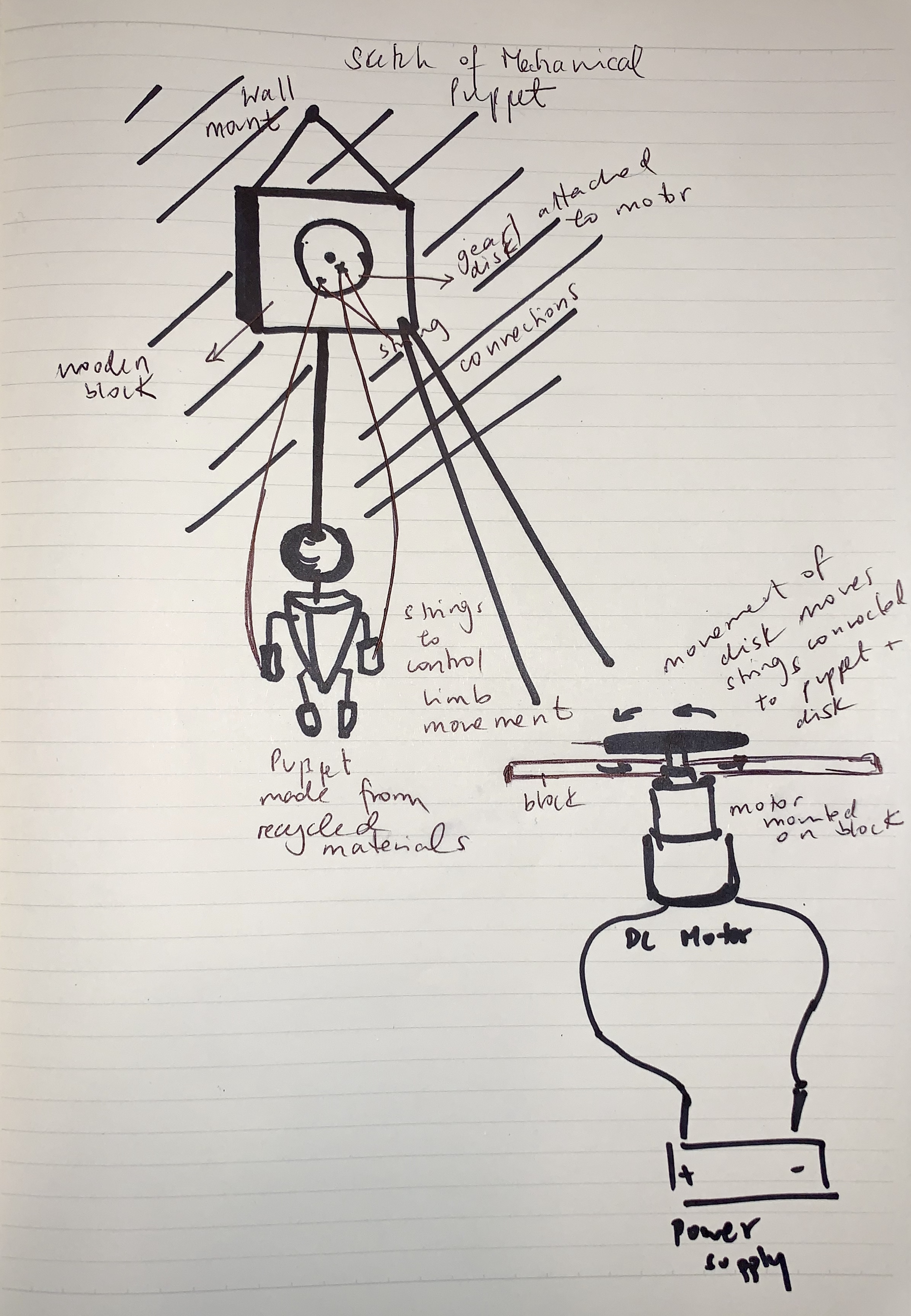
My design consists of two main components: the wall mount with the mechanical system and the puppet itself. Below I outline the steps followed to create each part.
Creating the Motorized Disk and Wall Mount
I began by measuring and cutting out a block of wood that would hold the motor and the puppet. The dimensions I used were 11cm in height and 16cm in width. I then created a point at the center marking where I would need to drill a hole for the motor (6mm). I used a table saw to cut out my block of wood. I then measured the diameter of the motor's shaft and found a drill bit of the same size. I used a hand drill to drill the hole in the middle. I then used a file to smooth the edges of the hole and create rounded edges for the wooden block.
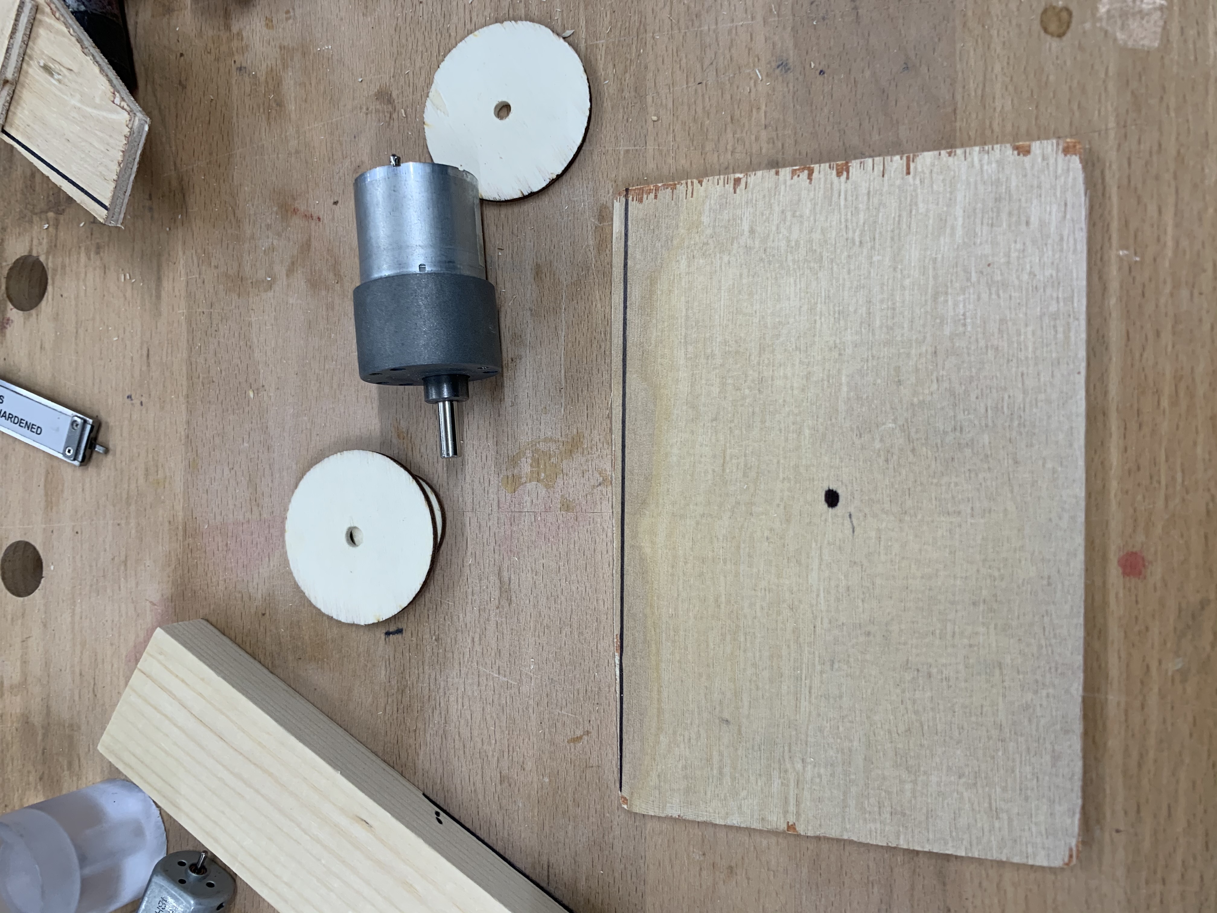
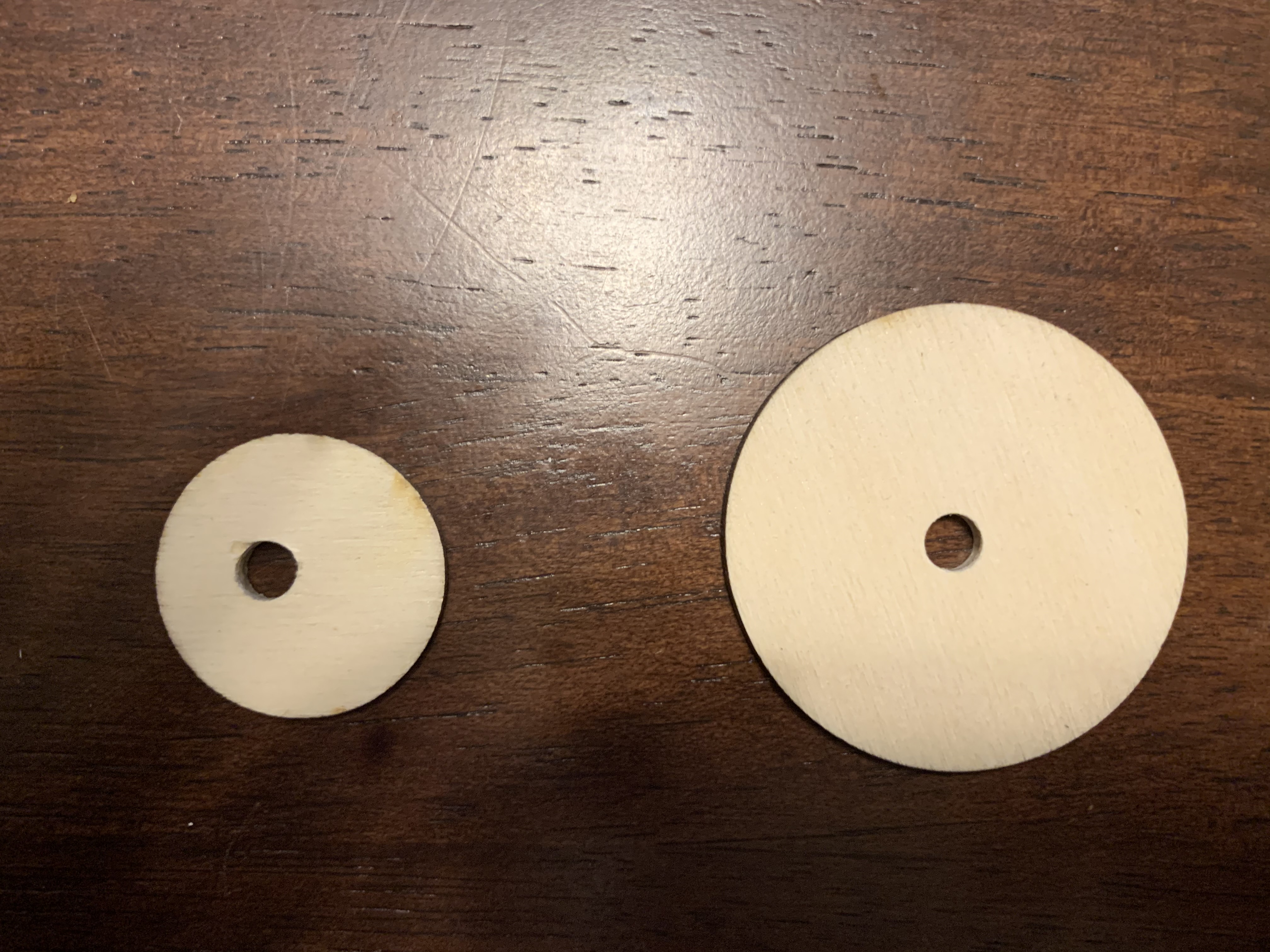
Next, I used the laser cutter to cut out two disks of diameters 6 and 3cm. I then used the hand drill to drill holes of 6mm in each (same size as motor shaft). See below.
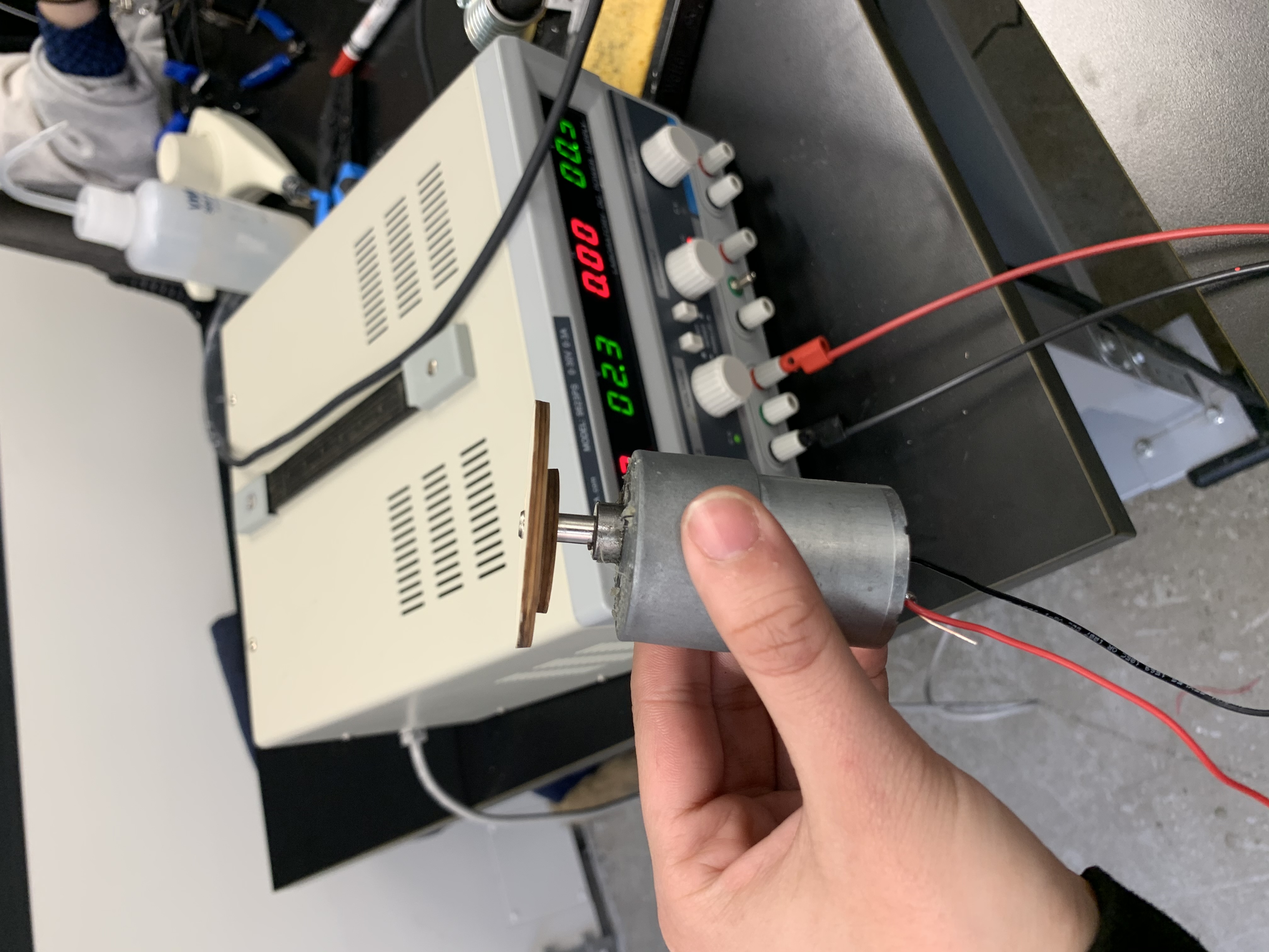
I then began creating the motor. For this, I first had to de-solder the brushes of the motor to remove the wires that were previously attached. I used de-soldering braid for this. Then, I soldered on a red and black wire on either brush. I tested it out by connecting to a power supply and it worked. I then pushed the shaft of the motor into the hole in my wooden block. It was tight enough to hold it without additional glue. I then attached both disks on the end of the shaft. I made sure that the motor only spun the disks and not the wooden base by using a file to slightly enlarge the hole in the wooden block. See below image of motor with disks attached.
Creating the Puppet
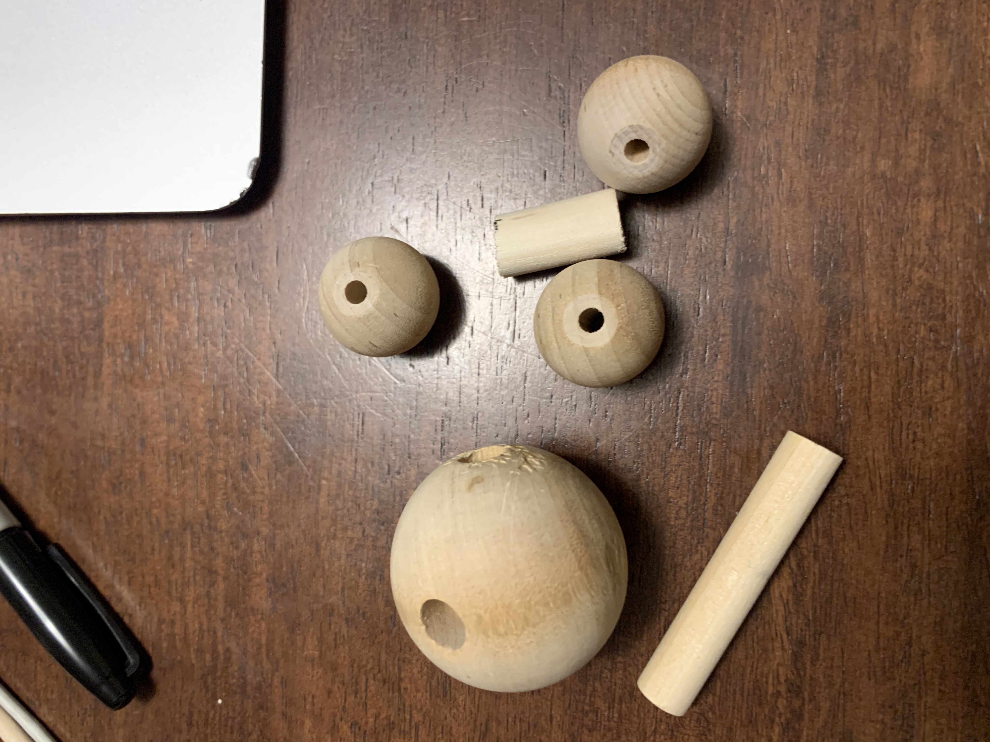
I then moved on to the next part of my sculpture: the puppet. I collected a few used pieces of wood that I found around the shop. These included wooden balls of different sizes, cylinders and blocks. I wanted to make my puppet out of recycled pieces because I was going to paint over it. See below.
I began by drilling a hole in the largest sphere (which would be the head of the puppet) through which I could attach a rod that would be connected to the top wooden block. I did this by securing the sphere in a clamp and using a hand drill with a drill bit equal to the diameter of the rod.
3D Model of Mechanical Puppet
Instead of finishing up the construction of the puppet, I decided to create a 3D model of what the finished product would look like since I had no access to a lab. Below I outline the steps to create a model of my puppet using Onshape.
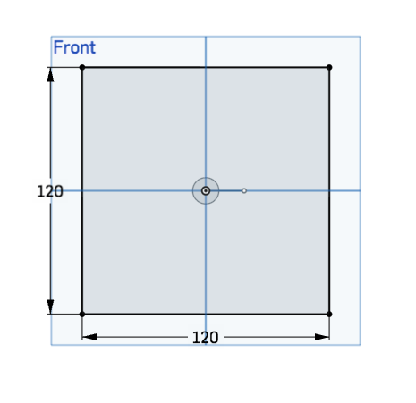
- First, I began by sketching a 120mm x 120mm square on the top plane. This will become the wall mount piece. Then, I drew a center point circle of 12mm in diameter that would become the rod attachment to secure the puppet to the wall mount.
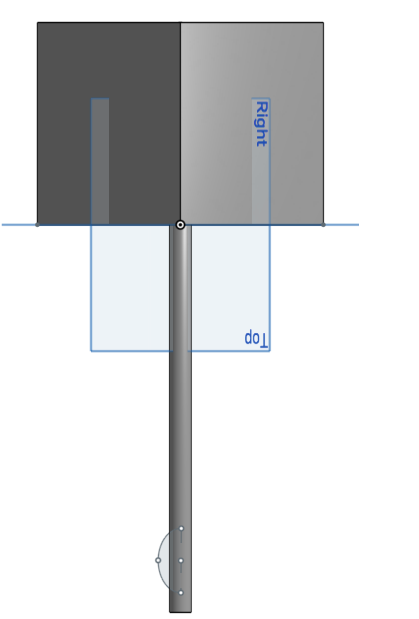
- Next, I used the thicken function to transform the base square to a 3D representation. I made the thickness of the square to 120mm to create a cube. I used the extrude function to transform the initial circle sketch into a rod part with 230mm in height.
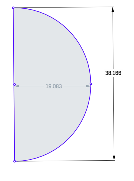
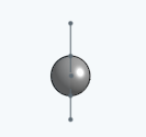
- Having created the base pieces, I began creating the puppet that would be attached to the rod. I began by creating a sphere to form the head of the puppet. I sketched a circle of 20mm radius with a vertical line at the center. I used the trim function to cut half the circle to create a semi-circle.
- I then used the revolve function to revolve the semi-circle around the vertical line axis to create a sphere.
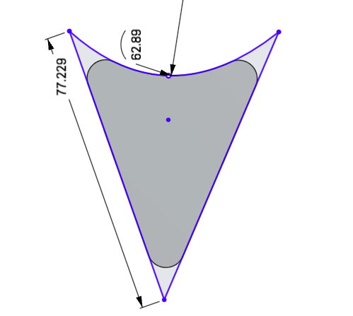
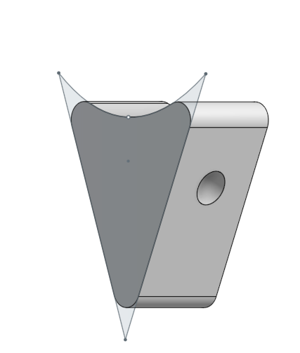
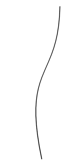
- For the body of the puppet, I drew two lines of 77mm to create an open triangle. For the top of the triangle, I drew a curved line to connect the ends. I then extruded the shape with a diameter of 30mm to create a 3d representation of the body.
Triangular sketch for puppet body:
- Next, I used a fillet feature to round the edges with a radius of 5mm. I created holes at the top-center of each side face of the body part to resemble sockets for where the arm parts will be placed. Using the hole function, I created two simple holes of 20mm in depth and 10mm in width that would intersect at the center.
- For the hands, I repeated the sphere step to create two spheres of 10mm in diameter. For the arm pieces, I created two thin pipe parts 20mm in length.
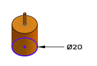
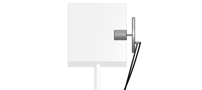
- I created a DC motor part that will be affixed in the wall mount. To do this, I drew a 20mm diameter circle with another 2mm diameter circle in the center. I extruded the larger circle to create a cylinder of 25mm in length. I then, extruded the top circle of 12mm to create the shaft component of the motor. I used the dimensions of a typical DC motor.
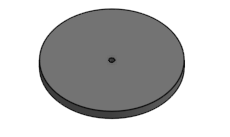
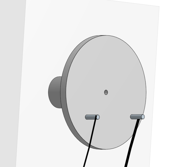
- I created the disc that will be attached to the shaft of the motor that will spin. I drew and extruded a circle of 70mm in diameter and a center hole of 3mm.
- I used the spline function to draw parts that resembled the strings that would affix the arms of the puppet to the disc. I extruded two 12mm cylinders from the disc part that would be used to attach the strings. I extruded the sketches to create what would resemble a string of 1mm.
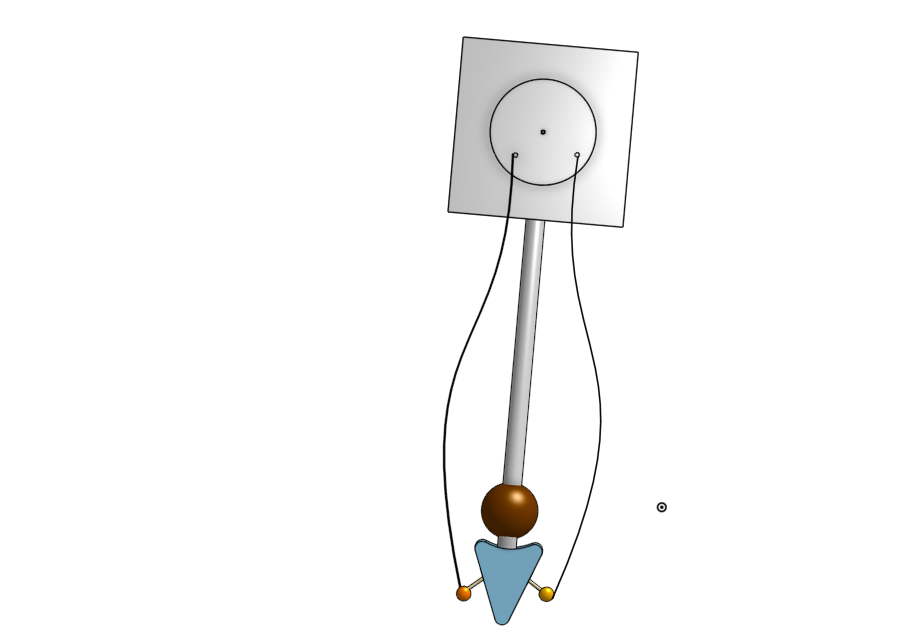
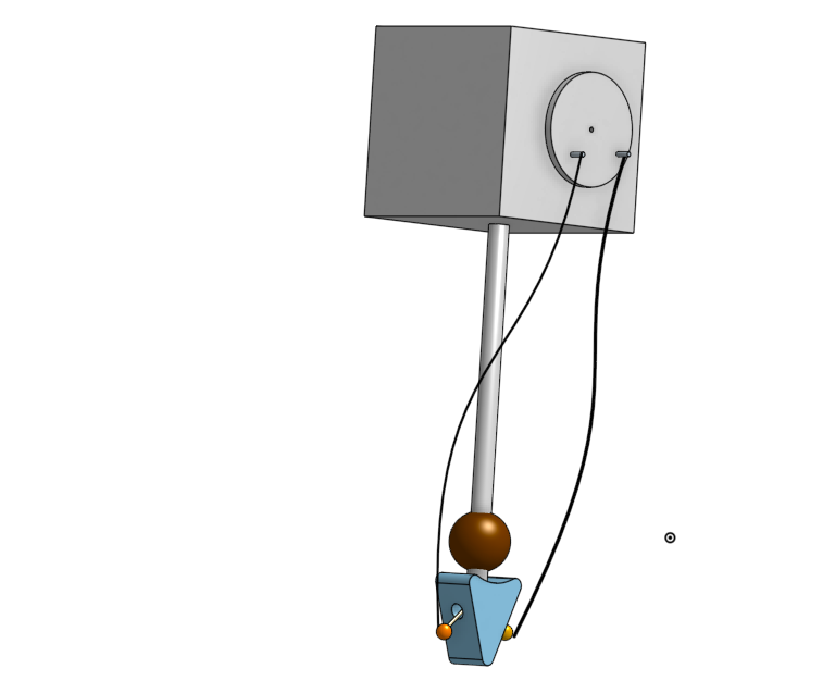
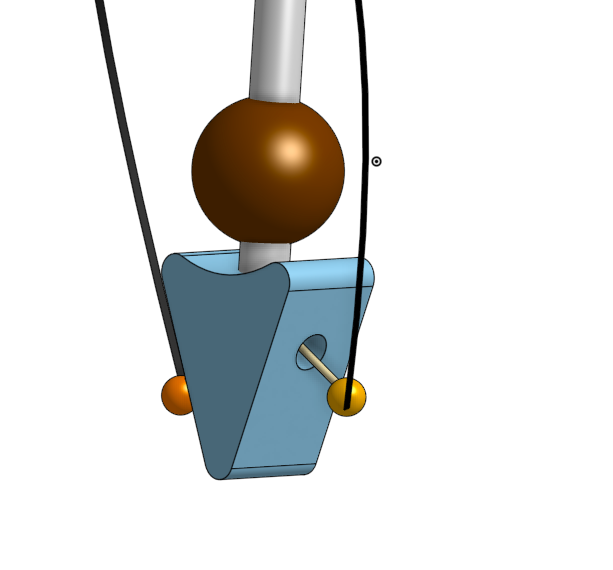
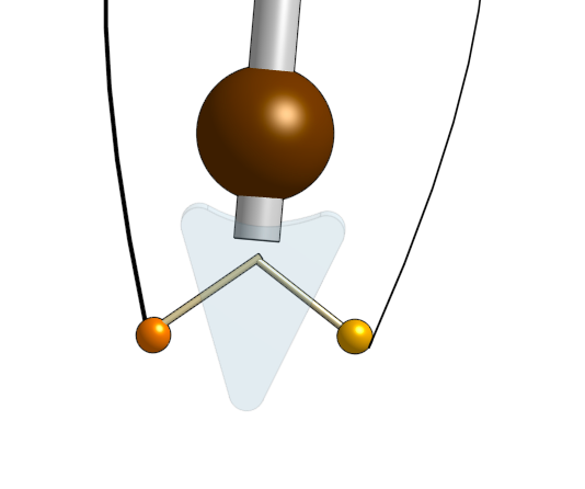
- Having created all the parts, I assembled them together. See images below for final assembly of finished product. The DC motor, when connected to a power source, would rotate the disc. The arms of the puppet are joined together in the triangular shaped hole. This means they would rotate in the same direction. So, both hands affixed to the disc via string would essentially rotate clockwise in the same direction as the disc spins.
Initial square and center-point circle sketch:
Extruded rod and wall mount parts:
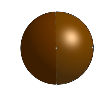
The image below shows the semi-circle sketch transformed into a sphere:
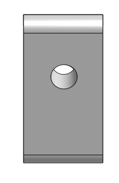
Extruded body part with arm sockets:
Hand parts
DC motor part:
Rotating disc:
String puppet connector:
Assembly of puppet:
The relevant files are available below for download: