Why this project?
After returning to Jordan, I was concerned by how the government had been handling the COVID-19 outbreak at home, particularly their communication strategies. Growing up in Jordan, I was used to the sound of air raid sirens that sounded throughout the country via a national alarm system that was controlled by the Department of Civil Defense. These air raid sirens were used to announce a national curfew in the event of threats of terrorist acts. We came to learn what the various signals or broadcasts by public officials meant. Currently, Each day, this national emergency siren system is being used to announce ban on movement, lift stay-at-home orders, begin national curfews or alert the public as to when they could go purchase their essential needs. The system is technologically obsolete, it does not cover the entire country and the wailing sounds are triggering. My project is an attempt to produce an alternative means of national emergency communication.
What are the problems with the existing technology?
The public siren system was implemented in 1982 and has not changed much. A study on Early Warning Systems for Disasters in Jordan describes it as "an achievement in its time" but now, the technology is "obsolete."
The system does not cover the entire country. Only three cities - Amman, Zarqa and Irbid - have decent coverage while other cities are completely out of signal reach.
The air raid sirens are triggering. They remind the public of wartime or incidents of threats to public safety.
The sirens sound at least twice each day (starting at 7am). They are loud, muffled and unpleasant. People have complained about the sounds that "blared at 7am."
Public officials make statements via loud speakers. These statements change each day. People have reported concern over the mixed messaging and lack of clarity.
Althought the public learned the meanings of siren tones over time, they do not convey much information or are they clear to those unfamiliar with them.
Different tools are used to communicate messages to the public in Jordan which includes TV, radio broadcasts, SMS notifications and posts online. There is no cohesion between the messages sent via each platform. Many people do not have access to these platforms. Thus, the existence of these different technologies, with no centralization, creates a lot of confusion and mixed-messaging.
What is the proposed solution?
Any proposed solution to the identified problems with Jordan's national siren system should have the following characteristics:
Low cost
Centralized messaging
Rapid response
High/total coverage
Clear signals/sirens/tones
Multiple types of signals
Remote operation
The Initial Concept: Remote Database and In-Home Device
My proposed solution consists of a two-part crisis communication tool: an in-home device and a central database. The database is controlled/administered by the governmental authority responsible for such crisis communication. Each individual/household receives a small, portable in-home device. The remote database communicates with all in-home devices at the same time to deliver various signals. The device will also have other emergency-related functionalities such as an SOS call button and two-way communication. This tool meets all the necessary characteristics of a solution to tackle the identified problems with the existing system.
What will it do?
Based upon the specifications listed above, the tool will include the following functionalities/features that will be useful in many national emergency scenarios:
A central database that will be able to communicate with all devices at the same time and send different signals. The database should be easy to use and require no technical skills to operate beyond pushing simple buttons. This will involve a 3rd party platform that acts as a general-purpose database for the IoT device.
A speaker that will be able to play audio messages sent from the database
Two warning lights to signal when the ban on movement begins or ends
An alert indicating a "seek out more information" message
An SOS/help button that will alert emergency personnel
-
An all-clear signal
-
A shelter-in-place alert
Wifi connectivity
Built-in power source
What will it look like?
Annotated CAD Drawing of Crisis Communication Device with Dimensions

Full View Animation of 3D Plastic Housing (100mm x 100mm x 100mm)
Full View Animation of 3D CAD Model
What components are required and how much do they cost?
Hardware
Annotated CAD Drawing of Crisis Communication Device with Dimensions
Full View Animation of 3D Plastic Housing (100mm x 100mm x 100mm)
Full View Animation of 3D CAD Model
What components are required and how much do they cost?
Hardware
To create a single device, the following materials are required. I included an estimate of the total cost of each hardware item, its dimensions and, where available, links to purchase the item from Adafruit.
-
Adafruit HUZZAH32 – ESP32 Feather Board ($20.00)(51mm x 23mm x 7mm)
-
Mini Metal Speaker with Wires - 8 ohm 0.5W ($1.95) (38mm)
-
Active Piezo Buzzer ($1.50) (12mm)
-
Round Tactile Button Switch ($0.40) (12mm x 12mm)
-
Three Ultrabright LEDS with 10mm diffused, color-tinted lenses ($1.00) (10mm)
-
USB Battery Pack - 5V Output ($15.00)(25mm x 91mm x 25mm)
-
Half-Size Breadboard ($5.00)(55mm x 85mm)
-
HOUSING?? ($5.00)(55mm x 85mm)
Software
-
Google Firebase Realtime Database
-
Arduino IDE Sketch
Estimated cost of a single device: $50
How will the device be built?
After returning to Jordan, I could not purchase the required electronic components. So, I had to make do with what I had. Thus, my prototype is merely a demonstration of some of the functionalities described above. The device consists of two parts: the housing and the electronic circuit. In what follows, I show how I created prototypes of each part.
Part 1: Circuit and Electronic Components
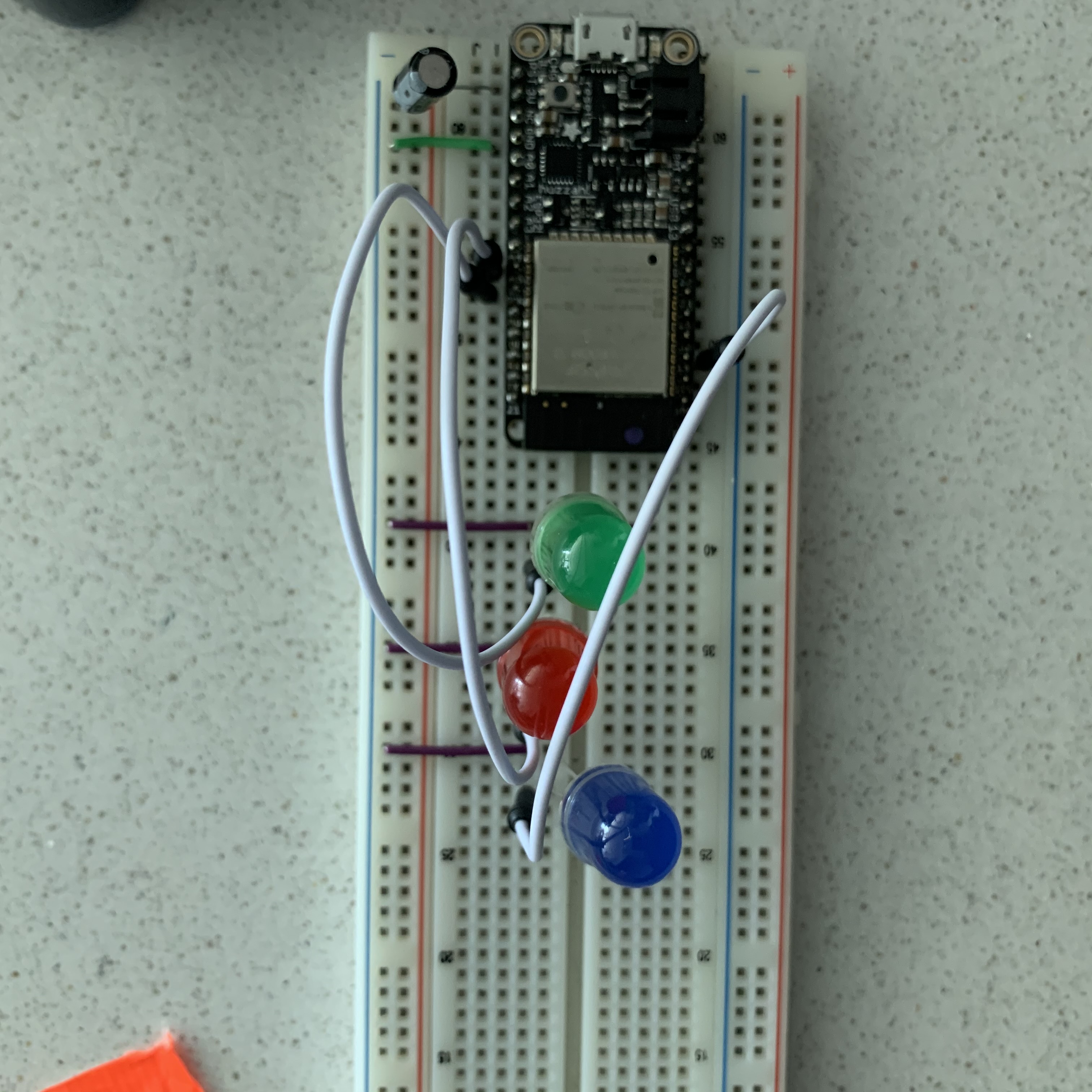
Given that I had limited access to electronic components, I built a fairly simple circuit to demonstrate some of the desired functionalities of the device. My curcuit consists of three output devices (10mm R, G, B LEDs) and a 10uF capacitor. Each of the LEDs is connected to GND and a digital pin on the HUZZAH32 – ESP32 Feather Board. I used the capacitor between RST and GND pins to stop the Huzzah from bootloading automatically (which prevented me from uploading my sketch). Once the sketch has been uploaded to the Arduino, the circuit will be powered via a USB 5V battery pack.
Model of Circuit Assembly (using Tinkercad)
Note: An Arduino Uno was used in the illustration. However, my project requires a Huzzah microcontroller. 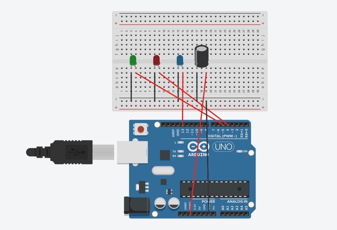
Image of Assembled Circuit
Part 2: Housing
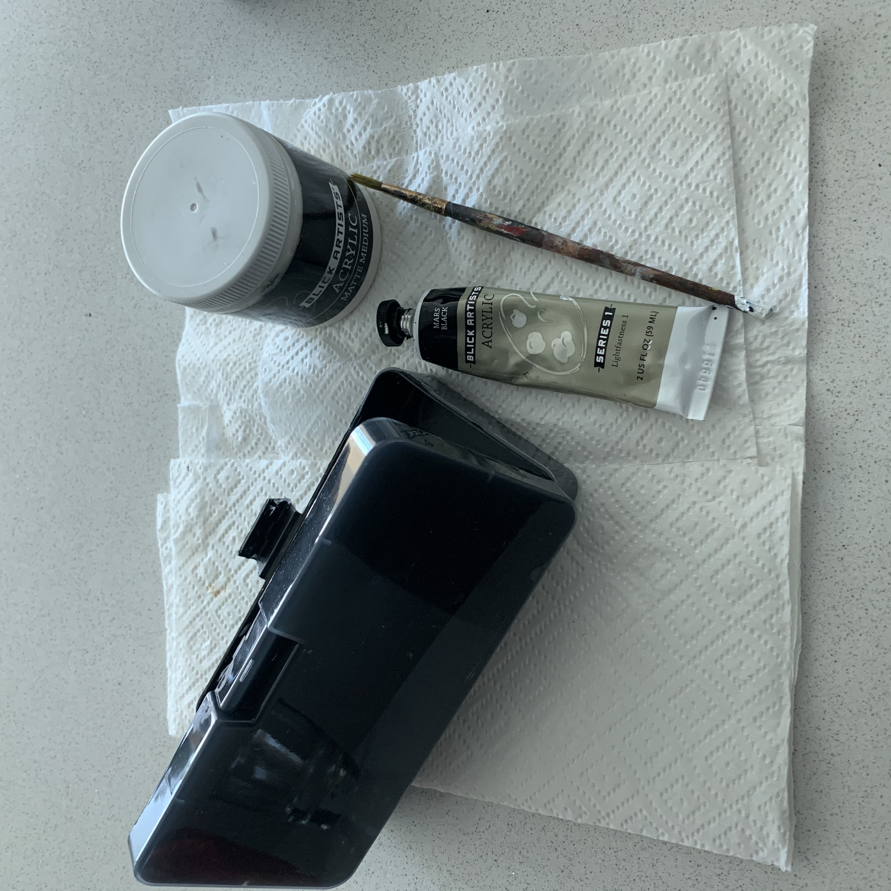
With limited supplies available, I created the housing from materials I found at home. I used a small plastic storage container as my base. For aestheitic purposes, I used black acrylic paint to paint the inside of the housing. I finished it with a matte medium acrylic finish. Once the circuit was asssembled, I affixed the breadboard with some duct tape to the top of the container (with a hole in the center). I also taped down the USB battery pack to the bottom.
Housing Prototype
Top View (Turned Off)
Inside View
Top View (Turned On)
How will the database be developed?
My final integrated database was developed via two stages. First, I built remote server using Firebase. Next, I created a personal webpage to make it easier and clearer to communicate with the device.
Part 1: Realtime Database
To communicate with the circuit , I created a remote server using Google Firebase. This 3rd party platform acts as a general-purpose database for my IoT project. A Realtime Database enables me to talk remotely with the device(s) from anywhere in the world. To do this, I created a new public Realtime database that communicated with the Arduino IDE to control the circuit I built. Find my public database here.
Crisis Communication Database Firebase Console
In my Arduino IDE, I created a simple sketch using the Firebase-ESP32 library and some digitalWrite() functions to receive the (input) (status of each LED from firebase) and produce an output (turn LED ON/OFF or blink). I created only one LED_STATUS field since I would be ceating my own user interface. This field consists of 8 possible inputs: turn green LED ON/OFF, turn red LED ON/OFF, blink blue LED, stop blue LED blinking, three LEDS flashing, three LEDs stop flashing. More fields will be added as I integrate more output devices into the circuit.
Part 2: Personal Webpage
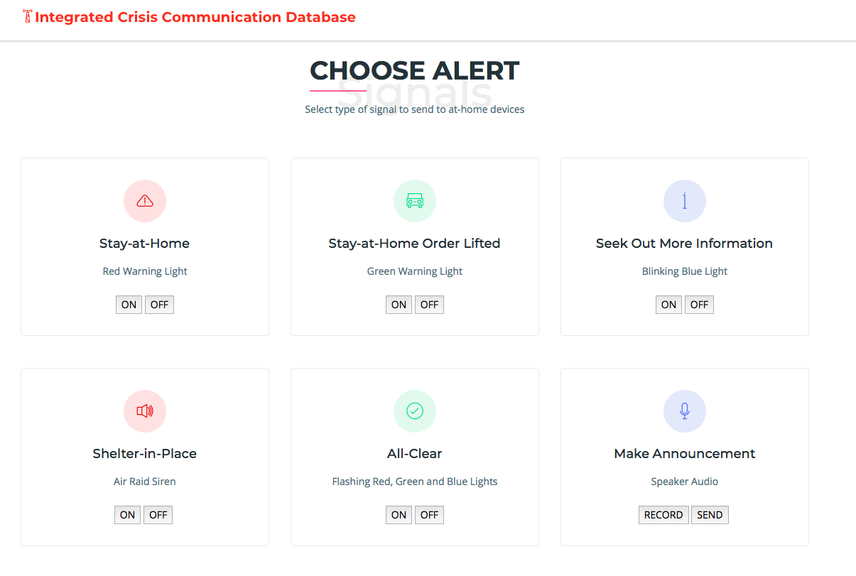
Having created the firebase database that one could use to manually change the input field, I wanted to create a smoother UI. I designed a simple webpage consisting of a grid of 2 rows x 3 columns. Each box in the grid is a container that houses one of the possible signals/alerts. For each container, I added two buttons (ON/OFF) that would remotely change the input status and control my LEDs. This UI is very user-friendly and consists of simple line icons, descriptions and clear buttons that are easy to use. As I integrate more output devices in my circuit and create new fields, I can add new containers to my webpage for easy user control. Find my database here .
Crisis Communication Database User Interface